If you have worked with Arduino and LCD (Liquid Crystal Display) for some time now, you would have been wondering how to connect two or more LCD to the Arduino board or Arduino Pro Mini board and perhaps simulate it with the Proteus CAD software. If this is the case, then take a cup of coffee, relax, and read this little piece that has been specifically crafted to connect two or more LCDs to Arduino in Proteus and other projects.
Recommended Posts:
After going through this article, you should be able to connect up to seven (7) individual LCDs to a single Arduino board (I used Arduino Uno in this tutorial) but you can use any Arduino board you are comfortable with provided it supports I2C protocol. The LCDs do not necessarily need to be the same. In fact, you can connect 16×2 LCD, 20×4 LCD, or 128×64 LCD to a single Arduino board at the same time and program them to display different parameters at the same time.
Check the video below:
Read Also: Getting Started with Arduino Programming for Beginners
Things needed for simulation
- Proteus ISIS software – Check this video link to install the latest version or fix errors with an existing one. This software will be used to draw the circuit that connects multiple LCDs to the Arduino.
- Arduino Core and Sensor Libraries for Proteus – Get them here or follow this video link to learn how to install them. This includes the Arduino Uno and LCD which can be used to simulate this multiple LCDs with the Arduino project
- 16×2, 20×4, or 128×64 Arduino LCD libraries for Proteus
- PCF8574A 8-bit I/O Expander chip for the I2C bus. This library is part of the default proteus components. The purpose of this component is to connect the LCD to Arduino using the I2C protocol.
Things needed for real design and implementation
- Arduino Development Board (Uno, Nano, Mega)
- 16 x 2, 20 x 4, 128 x 64 LCD with I2C Backpack
- Male to Female Jumper wires
This tutorial (How to connect multiple LCDs to Arduino in Proteus) focuses on Proteus simulation, however, the same principle works on real design as well. And believe me, the real design is even much easier than the simulation, therefore, being successful in the simulations means you could build the real circuit too.
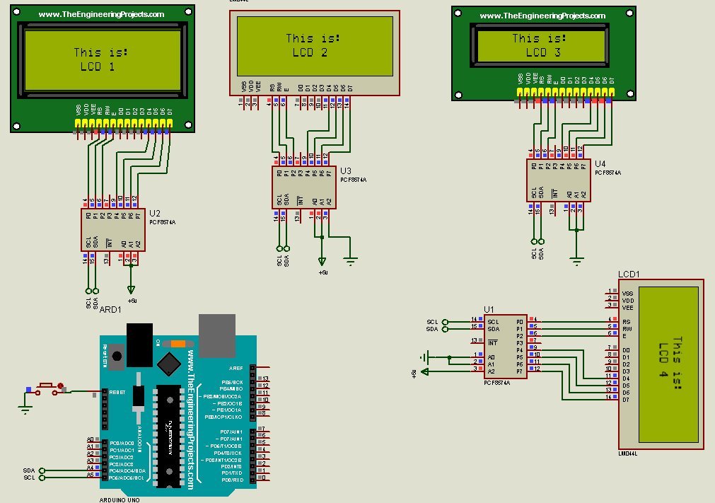
First, we will use the PCF8574A 8-bit I/O Expander chip for the I2C bus to connect to the various LCD. As the individual chip configuration allow the connection of up to 8 LCDs, I decided to tinker with it in Proteus to see whether it really works. Here, my primary goal is to interface 4 LCDs with two wires: SDA and SCL from an I2C bus. With direct Inputs / Outputs of a microcontroller, you need at least 48 lines to control all the displays.
Read Also: Arduino 4-Way Traffic system with Pedestrian button in Proteus
This is not feasible with the use of microcontrollers or development boards. For instance, the Arduino Uno is equipped with only 14 digital input/output pins and 6 analog pins. This means, in practice, the total usable pins of the Arduino Uno is 20 which is far less than the required pins of 48 to connect 8 pieces of LCD to the Arduino.
However, the option presented here will not only miraculously reduce the number of pins but also make interfacing, configuration, and programming much easier. In fact, we only need two (2) pins of the Arduino to connect the 8 LCDs. The funny part of this option is that none of the digital pins is used.
Use Proteus to connect the multiple LCD with the Arduino
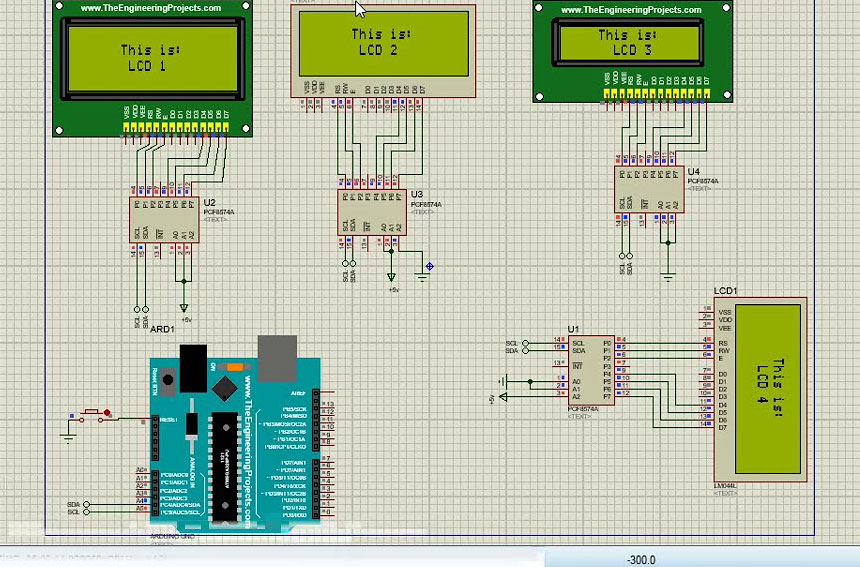
Open Proteus and draw the circuit to connect the various LCD to the Arduino Board as shown below.
Alternatively, you can download 8 awesome Arduino projects developed in Proteus software here. These projects come with both Proteus files and Arduino Sketch.
The circuit is super simple as can be seen above. Now upload the Arduino sketch and run the simulation. If you don’t know how to upload the Arduino code into the Arduino module in Proteus, or if you are just starting out in Proteus please refer to the tutorial below on how to install libraries and run your first Arduino/Proteus project simulation.
How does it work?
The trick employed here to connect the multiple LCD to the Arduino is the use of the I2C Chip PCF8574A. To get started we have to refer to the I2C in the Hexadecimal table.
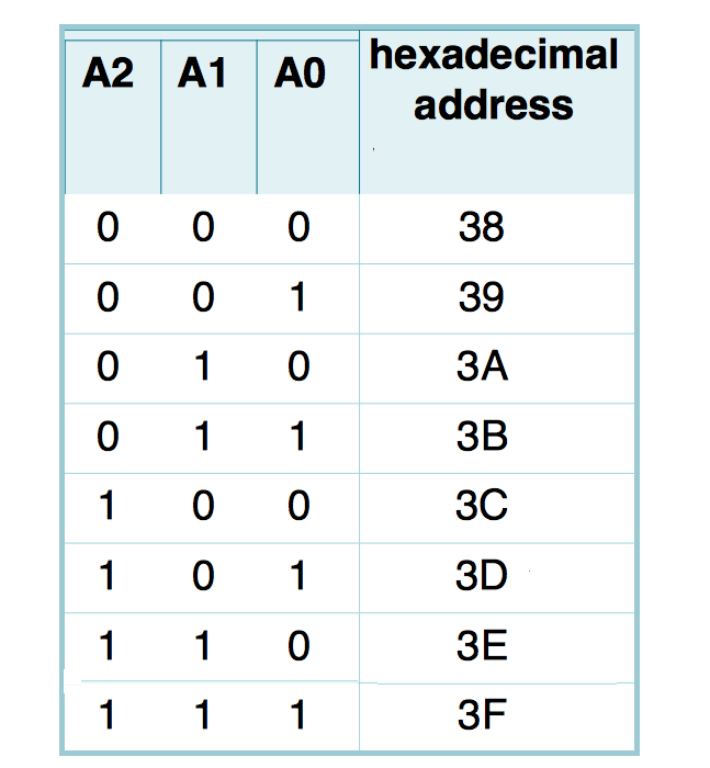
Here 0 corresponds to GND (LOW or 0V) and 1 corresponds to VCC (HIGH or 5V). This means shorting all the terminals A0, A1, and A2 and connecting them to grounding (GND) give 0 0 0 which corresponds to 38 in the Hexadecimal table.
Likewise, if all the terminals are connected to VCC or 5V rail, we get 1 1 1 which corresponds to 3F on the hexadecimal table. Referring to the image below, it is clear that the I2C chip (PCF8574A) that links the Arduino to the LCD 1 has all configurations pins connected to VCC. This gives it a hexadecimal address value of 3F.
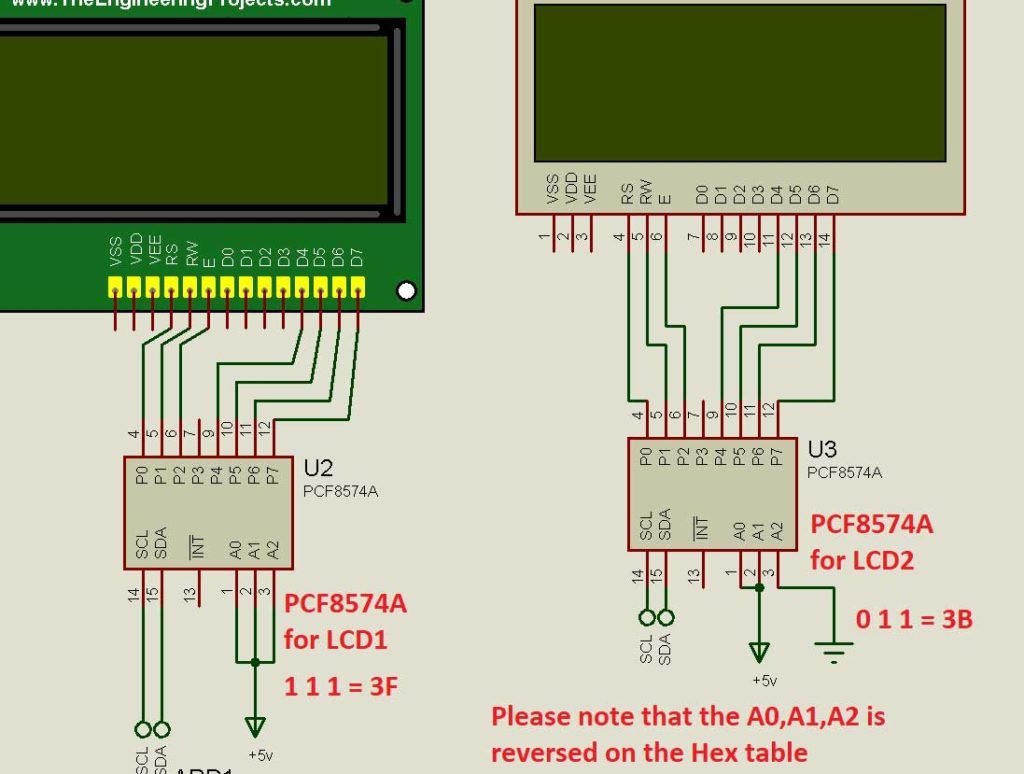
On the other hand, the PCF8574A chip has its A0 and A1 pins connected to VCC while the A2 pin is connected to GND. This gives a corresponding binary of 0 1 1. From the table, 0 0 1 is 3B.
Using a Real I2C Backpack
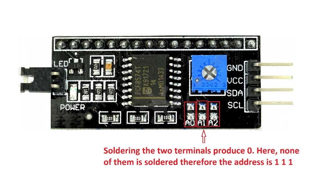
If you want to connect the multiple LCD to the Arduino with a real I2C backpack, you can refer to the image above. For 0 0 0 as your binary address, you solder together the two pins at A0, A1, and A2.
Once we have connected and obtained the corresponding hexadecimal number, we can proceed to the Arduino coding by stating them in the global variables. Check the code below:
#include <LiquidCrystal_I2C.h>

LiquidCrystal_I2C lcd1(0x3F,20,4);
LiquidCrystal_I2C lcd2(0x3B,16,2);
Since we have defined the individual LCD (LCD1 and LCD 2) we can print any character on both or the individual screen by calling the assigned name to the print function.
lcd1.print("HomeMade");
lcd2.print("Electronics");
As you can see above, the print statement for lcd1 is HomeMade and that of lcd2 is Electronics. This means when the code is run or simulated, LCD 1 will output “HomeMade” while LCD 2 displays “Electronics”. You may also like this post Getting Started with LoRa RYLR998 and Arduino. It will help build wireless projects around Arduino.
Conclusion
In this tutorial, I have demonstrated to you how you can connect multiple LCD to Arduino. The Arduino Uno can control 8 LCDs at the same time using the I2C bus. It doesn’t matter whether the LCD is 128×64, 20×4, or 16×2 type. The most important thing is the interpretation of the I2C table given above. If you have any questions, suggestions, or circuit/simulation requests, kindly leave it/them in the comment section. I will be glad to assist you.


nice tutorial, i’ve been loking for this so far.
thanks for sharing..
Glad I could help
Can I run the simulation with 4 different LM041L without knowing their specific i2c bus addresses?
If yes, how will I get their address to implement in the Arduino ide.