Table of Contents
What is this FM transmitter Circuit About?
There are so many FM-related questions that always catch headlines, among these questions are; How does a Bluetooth FM transmitter for a car circuit work? What are FM transmitters used for? What are FM transmitters and Receivers? Why do we use transmitters?
If you are also asking similar questions, then you are not alone. Sir Boateng Online has your back because this post is all about DIY FM transmitters (Do-It-Yourself FM transmitters). There will also be a detailed explanation of what the FM transmitter is.
If you are interested in microcontrollers, you can start with Arduino Programming for Beginners. or ESP8266 Development Board programming.
What is Modulation
The frequency range of an audio signal (voice and musical instruments) is 20 Hz to 20 kHz. This frequency can only travel a few meters from its source. However, we must transmit this audio signal to our audience, who is located a long distance away from us. This is only possible with high frequency, which serves as the foundation of an FM transmitter.
Handpicked related articles for you:
The problem of long-distance transmission gave rise to modulation. The phenomenon of modulation is the combination of an audio signal and a high-frequency signal (called the carrier). This combination is then broadcast over the air, as illustrated below.
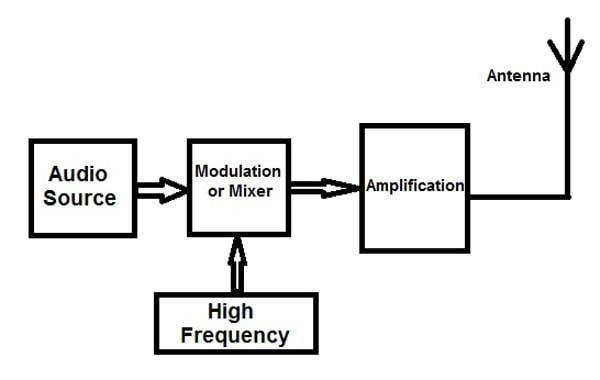
Modulation is, therefore, the process of combining information (audio or data signals) and high frequency (carrier) for transmission.
A circuit at the receiving end has a specialized circuit to separate the audio signal from the high frequency. This circuit is called a demodulator.
There are numerous types of modulation in all aspects of telecommunication, but the two most common types of modulation in radio waves are frequency modulation and amplitude modulation.
What is FM?
FM means Frequency Modulation: It is the type of modulation used for an FM transmitter. With this type of modulation, the audio frequency modulates the carrier frequency.
There are various types of FM transmitters; some are very powerful, and capable of transmitting over long distances, while others are stable with advanced PLL control devices. Aside from their power and stability, some FM transmitters use RDS (Radio Data System) to attach text information (such as the name of the station, and its frequency).
Recently, technology has made it possible to use Bluetooth FM transmitter modules as a method of transmitting FM signals. Using a few tiny semiconductor chips, one can transmit high-quality audio and data signals with this Bluetooth FM transmitter.
Building a Simple FM Transmitter Using Only Transistors
The project focuses on designing a simple FM transmitter circuit that can transmit radio signals within a range of 1 to 2 kilometers if a good antenna is used. Unlike, Bluetooth FM transmitters, this circuit uses only a few transistors to transmit the audio signal from one place to another using the frequency modulation spectrum.
The first two transistors Q1 and Q2 form a normal audio pre-amplifier. This increases the audio signal before feeding it to the output stage. The amplified audio signal to be propagated is then passed to the base of transistor Q3 through the 0.47uf capacitor (C5).
Circuit diagram.
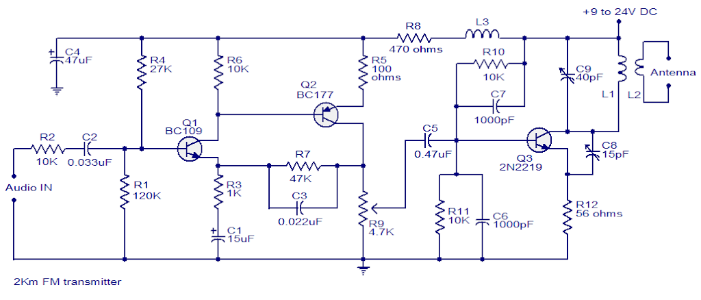
The resistors are all used for biassing. The output transistor (Q3) modulates the oscillating frequency with the audio signal and also serves as the power amplifier’s final stage. The tank circuit’s capacitor C9 and inductor L1 perform the passive oscillation.
Mutual induction is used by inductor L2 to induce the radio frequency from the tank circuit to the antenna. This is referred to as electromagnetic induction.
Things To Consider in this FM transmitter project.
- As in all radio circuits, you have to follow PCB design rules. That is to choose a good and quality Printed Circuit Board (PCB).
- Your circuit track must be free from stray capacitance as u keep all component pins short as possible.
- You can supply this circuit with a range of DC voltages from as little as 6v to a maximum of 12V.
- L3 is 220uH. You can make one with the number 28 SWG 30 turns on 6mm diameter former with 5mm long. This is not critical as you can use any inductor available
- L1 and L2 are on the same core close to each other. L1 is 3 turns of 1mm enameled copper wire on a 10mm diameter plastic core. L2 is 2 turns of 1 mm enameled copper wire.
- You can vary the frequency from 88 to 108 by adjusting the trim-pot capacitor (C9).
- The audio gain is controlled by the variable resistor (R9.
- You can adjust the trim-pot capacitor (C8) for RF gain and optimum performance.
- For this type of FM transmitter, using a stabilized DC source such as a battery for powering the circuit will reduce noise to a great margin.