Sir Boateng
  • ELECTRONICS
  • TUTORIALS
  • ARDUINO
  • EDUCATION
    • GES Resources
    • NTC Resources
  • APPLIED ELECTRICITY
No Result
View All Result
Sir Boateng
  • ELECTRONICS
  • TUTORIALS
  • ARDUINO
  • EDUCATION
    • GES Resources
    • NTC Resources
  • APPLIED ELECTRICITY
No Result
View All Result
Sir Boateng
No Result
View All Result

ESP8266 Development Board Programming with Arduino IDE

by Boateng
15th February 2023
in Arduino Projects, Tutorials
161 12
0
198
SHARES
618
VIEWS
Share on FacebookShare on TwitterShare on WhatsApp

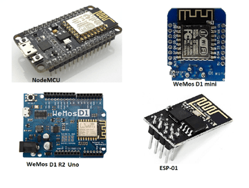
The NodeMCU and Wemos D1 R2/mini development boards use the well-known ESP8266 ESP8266 Development Board WiFi chip. The ESP8266 appears to be programmable in the same way that any other microcontroller such as the Arduino Uno is.

Its clear advantage over the Arduino or PIC is its ability to connect to the Internet via WiFi. The ESP8266 Wi-Fi board, on the other hand, has limited pins, despite the fact that the chip itself has a plethora of output ports.

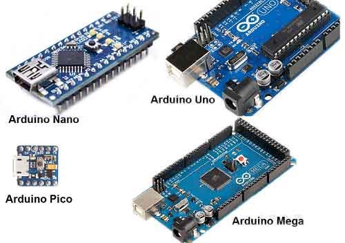
The NodeMCU overcomes this limitation by including ten GPIO pins capable of generating PWM, I2C, and a 1-wire interface. This ESP8266 development board closely resembles an Arduino Nano.

Another advantage of this board as an Arduino is that you can programme it directly from your PC or Mac! That is exactly what I will demonstrate in this tutorial. Let’s cross our fingers and follow the steps below.

Recommended Posts:

  • Arduino Uno Programming for Beginners
  • Arduino Pro Mini for Beginners (AVR Atmel Atmega328p)
  • Control home appliances with voice Using Google Assistant
  • Arduino vs Raspberry Pi: Which one is good for your project?

Article Navigation

  • Step 1: Insert your ESP8266 Development Board into your computer USB port
  • Step 2: Launch the Arduino IDE
  • Step 3: Test your ESP8266 Development Board, Make an LED blink.

Step 1: Insert your ESP8266 Development Board into your computer USB port

To connect the board, you’ll need a USB port micro B cable. After connecting the board to the USB port, the blue LED on the board began to flash. The device driver for your board should have been installed by now. If your computer isn’t detecting the board, you might need to download and install the driver from this page.

SEE ALSO:  Arduino vs Raspberry Pi: Which one is good for your project?

Step 2: Launch the Arduino IDE

Download and install the most recent Arduino IDE from arduino.cc. If you already have the IDE installed, make sure your version is at least 1.6.4 before proceeding. Navigate to File > Preferences.

The preferences window will appear, and in the “Additional Boards Manager URLs” field, type (or copy-paste) the following link without the quotes: “https://arduino.esp8266.com/stable/package_esp8266com_index.json“. To close the window, click OK. check the diagram below.

Arduino IDE settings for wemos d1 mini esp8266 esp 12e development board
Arduino IDE settings: Click to enlarge

Then navigate to Tools > Board > Board Manager. Scroll down to the entry “esp8266 by ESP8266 Community.” Look for the install button in the lower right corner after clicking that entry.

Wait for the installation to complete. Congratulation! The ESP core board library is now installed and integrated into the Arduino IDE. You can now begin tinkering with your Wi-Fi board.

Step 3: Test your ESP8266 Development Board, Make an LED blink.

Let’s put our ESP Wi-Fi board to the test by making an LED connected to one of the digital pins blinks. But first, you should be aware that the pin names printed on the board and the pin names we’ll be using for our programme differ slightly. I’m working with NodeMCU V1.0. See the pinout diagram below.

NodeMCU ESP8266 Development Boardpinout
NodeMCU pinout: Click to enlarge

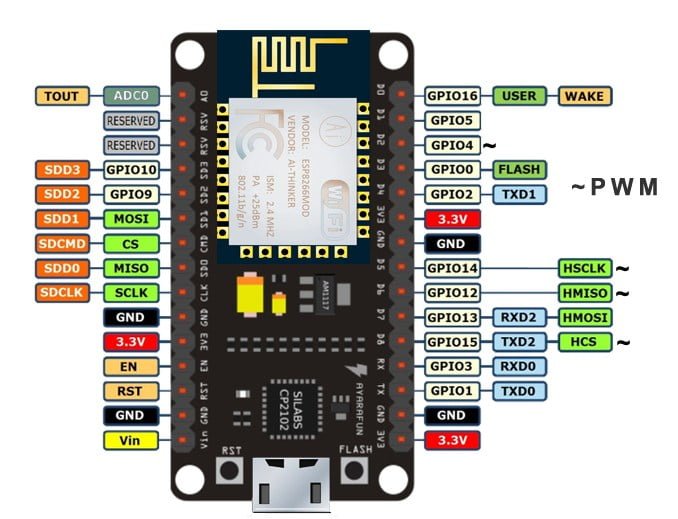
In this tutorial, I wired the LED to D7, as shown on the NodeMCU Esp8266 board. As seen in the image above, D7 represents GPIO13. The following code is essentially the Blink sketch from the Arduino example:

// the setup function runs once when you press reset or power the board
void setup() {
  // initialize digital pin 13 as an output.
  pinMode(13, OUTPUT);
}

// the loop function runs over and over again forever
void loop() {
  digitalWrite(13, HIGH);   // turn the LED on (HIGH is the voltage level)
  delay(1000);              // wait for a second
  digitalWrite(13, LOW);    // turn the LED off by making the voltage LOW
  delay(1000);              // wait for a second
}

Enter or copy the code above into the text editor pane of the Arduino IDE. Press the upload button. If everything is in order, the “Done Uploading” text will appear beneath the IDE text editor.

SEE ALSO:  How to install all TM1 Laptop drivers

Bingo! here we are, it worked!

Even though I used the nodeMCU for this tutorial, the Wemos d1 mini, and the Arduino wifi can also be used. If you have any problem connecting the ESP8266 Development Board, esp8266 esp 12e development board, nodemcu esp8266 development board or Wemos esp8266 development board to the Arduino IDE, use the comment box to ask for help.

You may also read more about Arduino programming from this link.

Join Our Tech & Edu Forum
Tags: arduino projectsesp8266nodemcu
Previous Post

Arduino Bluetooth Locking System with MIT App Inventor

Next Post

FM transmitter Project Using only transistors

Boateng

Boateng

Leave a Reply Cancel reply

Your email address will not be published. Required fields are marked *

Recent Posts

A picture of grammarly premium and grammerly free, get grammarly premium cookies for free - grammarly premium cookies daily updates free download - use grammarly premium free.png

How to Get Grammarly Premium Cookies for Free in 2023

23rd March 2023
This picture shows all Category C Schools In Ghana - Best Category C Schools in Ghana along with the regions of the location . jpg

Full List of Category C Schools in Ghana

2nd March 2023
A picture of grammarly premium and grammerly free, get grammarly premium cookies for free - grammarly premium cookies daily updates free download - use grammarly premium free.png

Get grammarly premium for free using Cookies

6th March 2023
How to start a blog and earn money online

How to start a blog and earn money online

2nd March 2023
Samsung Galaxy S23 Ultra 5G: All You Need to Know

Samsung Galaxy S23 Ultra 5G: All You Need to Know

Overview of High School Education in Ghana

Overview of High School Education in Ghana

24th February 2023

Categories

  • Applied Electricity & Electronics (4)
  • Arduino Projects (8)
  • Blogging (4)
  • Business (4)
  • Education (27)
  • Electronics (21)
  • GES Resources (12)
  • NTC Resources (3)
  • Product and Service Reviews (4)
  • Proteus (2)
  • Tutorials (21)
Sir Boateng Online

Sir Boateng Online is a platform for electronics projects, tutorials and educational resources. Aside creating tech tutorials, we also provide GES and NTC resources such as teaching syllabus, lesson notes, scheme of work and NTC trial questions.

Popular Categories

Applied Electricity & Electronics Arduino Projects Blogging Business Education Electronics GES Resources NTC Resources Product and Service Reviews Proteus Tutorials

Stay Connected

  • About Me (Sir Boateng Oduro)
  • Forum
  • Disclaimer
  • Privacy Policy
  • Terms and Conditions

© 2023 Sir Boateng Online - Developed by Lizbotech.

No Result
View All Result
  • ELECTRONICS
  • TUTORIALS
  • ARDUINO
  • EDUCATION
    • GES Resources
    • NTC Resources
  • APPLIED ELECTRICITY

© 2023 Sir Boateng Online - Developed by Lizbotech.

Welcome Back!

Login to your account below

Forgotten Password?

Retrieve your password

Please enter your username or email address to reset your password.

Log In