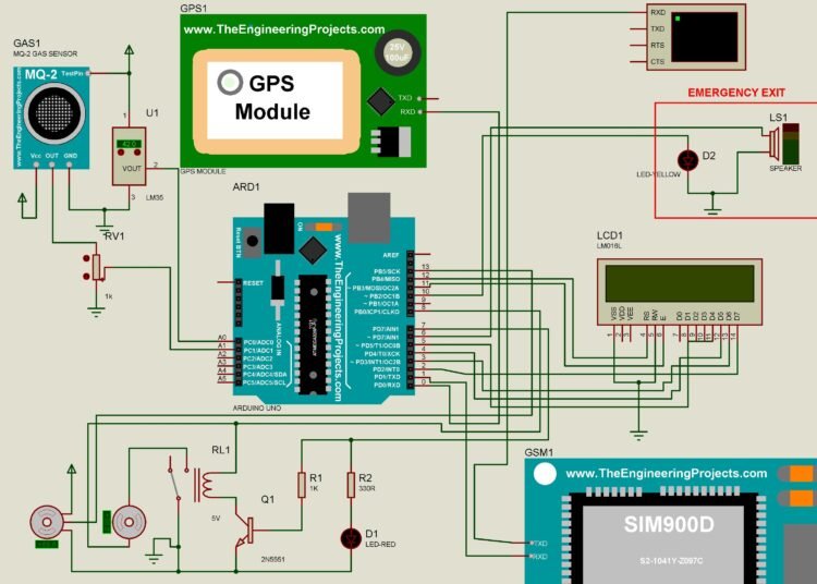
The project presented here is a GSM Based Fire and Smoke Detection and Prevention System With GPS Location Coordinates designed and simulated in Proteus. The system detects fire, gas, or smoke and sends an SMS with the location of the premises to the owner or firefighters.
The system can also shut down all gas valves and pump out water or an appropriate extinguisher if connected. This is a simulation but can also be physically implemented with real functional components.
DOWNLOAD GSM BASED FIRE AND SMOKE DETECTOR PROJECT
Check the demonstration of the project below:
Fire alarm system plays an important role in maintaining and monitoring the safety of all kind of environments and situations. However, the usability of many existing fire Alarm systems is well known but could be produced at a high cost. Subsequently, it is not affordable for low-income users.
Also, check these hand-picked related projects and articles for you:
Therefore, the main objective of this GSM Based Fire and Smoke Detection and Prevention System With GPS Location Coordinates is to make a fire control system at a low cost. The project has three main systems the detection system the monitoring system and the appliance system.
READ ALSO: Arduino Water Level Monitor and Controller in Proteus
The detection system operates as the fire detector and smoke detector. This paper discusses the design and implementation of a fire alarm system using the ARDUINO UNO R3 which operates the entire system.
The detectors are placed in parallel at different levels. Any signal from each detector at any level is monitored using a monitoring system.
The appliance system has components like GSM for sending SMS, a buzzer for alarming, servos for an automatic lockdown of doors in emergency exits, a motor serving as a fire extinguishing pump to stop the fire, and a GPS module to indicate the location where the fire has occurred.
The entire system is controlled by a microcontroller, in this the Arduino Uno. The microcontroller is programmed using C-Programming language with ARDUINO IDE.
The system can detect smoke, flame, heat, etc. sensed by the respective modules, followed by the monitoring system which indicates smoke, light, flame, heat, etc. at a particular level.
Finally, when the sensors from each level triggered are individual, the main Buzzer operates and an SMS is sent. The LCD will indicate the affected area while at the same time the emergency exit servo motor, as well as the water pump motor, is activated. Read the full project here


the gps coordination number is 000 on the display
what is the reason behind?
1. what is the main purpose of servo motor for this project?
2. why the DC motor and Servo motor can not stop rotating after temperature decreasing by the simulation of LM 35 sensor ?
please send me soon the answer if you are online.
[email protected]
servos for an automatic opening and locking of doors in emergency exits, and the motor serves as a fire extinguishing pump
dear Sir Boat great Thank u !!!
Dear how many a distance/radius in meter the DC motor sprinkling the water
That depends on the motor itself
let you estimate
As I said, you can’t make any estimate with the distance because the motor used will be different across the board. Also, the sprinkler nostril plays another role in the distance. The controller is just to turn the motor on or off
thank you alot!
Dear Sirbo
is GPS module signal is input to Arduino or output from Arduino. Let you give me persuasive information.
best regards!
input to Arduino. You may be thinking about why the RX pin is only used. Yes, it is a defect of the GPS library. The library was coded to assume the tx pin is already connected virtually.
Dear Sir boat
I would like to thank you so much I will communicate on another time any issues until then goodbye
sincerely !!!
is there any future work for this project? additional technology?
Yes, the inclusion of automatic fire extinguishers and web-based notification
Sir ,Can I get .c file of code
I will update the article and include any other relevant information such as PCB and complete circuit diagram later. For the mean time you can convert the .ino to .c file for consumption.
Sir Boat,if i add a flame sensor how must i instruct my arduino to operate with both the gas and flame sensor together?
Got it all good
Alright. Glad it is working for you.
please help me if you a full document about this title.
Thanks for your comment! I’m really glad you found the post helpful. At the moment, I don’t have a full document on that topic, but I’ll definitely consider putting one together if there’s enough interest. Stay tuned for more updates!
please help me if you have full document about this title.
Thanks for your comment! I’m really glad you found the post helpful. At the moment, I don’t have a full document on that topic, but I’ll definitely consider putting one together if there’s enough interest. Stay tuned for more updates! Our new Tech related website is at https://diygh.com/blog/