How to Build and Control Home Appliances Using Google Assistant | Adafruit | IFTTT | DIY | IOT | NodeMcu | ESP8266
This project is about building Google Home Appliance Control using Google Assistance and NodeMCU
Welcome to Sir Boateng Online Tutorials powered by ElectroTek Engineering!. If you are on this page, then it is no surprise that you are curious to know, design and construct your own, perhaps your first Nodemcu-based home automation using google assistant and MQTT broker. Of course, you are in the right place.😎
Disclaimer!, All the information on this website – www.sirboatengonline.com – is published in good faith and for general information purposes only.
Even though we strive for the best, Electrotek Online does not make any warranties about the completeness, reliability, and accuracy of this info…..read more
Warning!, This project incorporates a high alternating voltage source (110V / 220V). DO NOT attempt this project if you are NOT familiar with electric wiring and safety.
I will be (as I have always been) fair to remind you that, as engineers, safety practice is always paramount, and precautionary measures must always be adhered to. Just ” One flash and you are ashes, therefore, better safe than sorry”
Should you decide to start from the basics, you can read the “Introduction to Arduino programming” for more understanding of microcontrollers and electronic components.
Things Needed for the Google Home Appliance Control Project
- NodeMCU ESP-12 V3. get it at Aliexpress
- 5V 2A DC Power Supply Adapter. get it at Aliexpress
- 4 in 1 Relay Module. get it at Aliexpress
- 5x Light Emitting Diodes
- Connecting wires, lamp holder, and 13A socket.
- Router or Phone Hotspot
- A device with google assistant enabled (Android phone,
Iphone ) - Laptop or Desktop PC for programming and doing online registration
Software and Registration: Google Home Appliance Control
- Adafruit MQTT broke. Register here
- IFTTT account. Register here
- Google account (Gmail). Your normal Gmail. Register here if you don’t have a Gmail account
- Self – Motivation, determination, and time, yes! I mean your time.
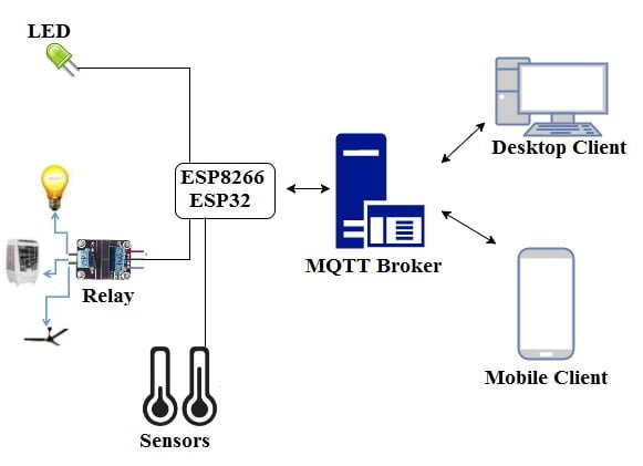
BRIEF BACKGROUND THEORY
What is MQTT?
MQTT ( Message Queuing Telemetry Transport) is an ISO standard for a machine-to-machine or “Internet of Things” connectivity protocol on top of TCP/IP.
It is designed for connections with remote locations where the network bandwidth is limited or where minimum resources are required.MQTT allows extremely lightweight publish-subscribe-based messaging transport.
The publish-subscribe messaging pattern requires a message broker. Our first step to get MQTT working is, therefore, to choose a broker. The broker can be online or offline depending on what project you are currently doing and the level of privacy you want.
The broker will perform all the background magic while we concentrate on the projects’ performance and extended functionality. in this project (Google Home Appliance Control), I used the Adafruit MQTT broker.
IFTTT
IFTTT (also known as If This Then That) is a free web-based service to create chains of simple conditional statements, called applets. An applet is triggered by changes that occur within other web services such as Gmail, Facebook, Telegram, or Instagram.
For example, an applet may send an e-mail message if the user tweets using a hashtag, or copy a photo on Facebook to a user’s archive if someone tags a user in a photo. In addition to the web-based application, the service runs on iOS and Android.
In this project, I will use IFTTT to interface adafruit.io to Google service to receive instructions from google assistant. Enough of the theories now let’s get to work.
STEP 1: HOOKING UP THE DIFFERENT COMPONENTS
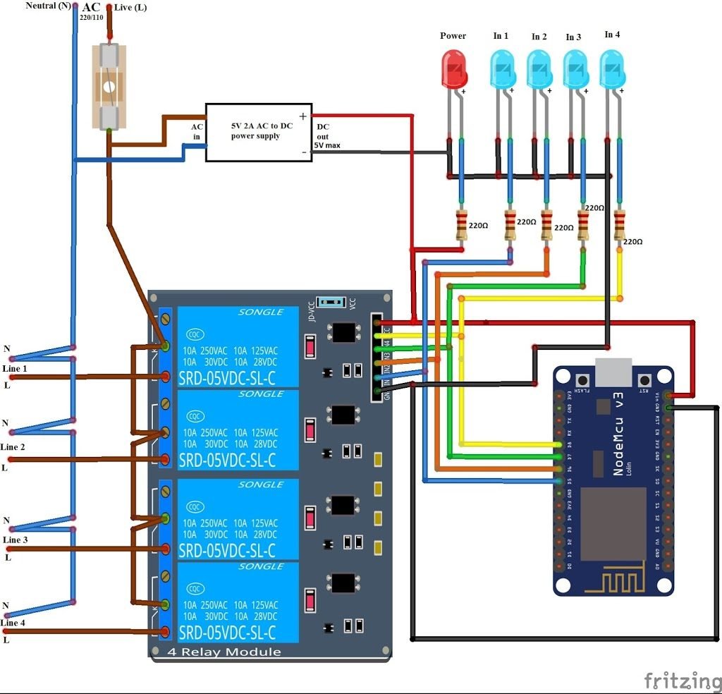
Hook up the circuit as shown above. Even though I used pins D5, D6, D7, and D8 to connect the relay module, you can choose to use any pin for the relay module provided you define them in your sketch (programming).
You may ignore the 110V/220V AC source for now since we will use the 5V DC from the USB port of your computer.
STEP 2: SETTING UP YOUR ADAFRUIT MQTT/ IO
Adafruit IO is an Internet of Things (IoT) platform developed using the Message-Queue-Telemetry-Transport (MQTT) Protocol.
As has already been discussed in this post, MQTT is a lightweight protocol that allows several devices to connect to a shared server, normally called the MQTT Broker, and then subscribe or write to customized topics.
Not only does Adafruit provide a free MQTT service but they also allow users to customize dashboards that let them directly manipulate or view their current value of each topic.
Recommended Articles:
Adafruit IO is the ideal MQTT broker since it is web-based that makes monitoring and controlling of your various IoT projects easily accessible using just a web browser.
At this point, I will assume that you have created your Adafruit IO account. If not visit this page and create your free Adafruit account. Once you are done creating your Adafruit account, you should be redirected to the home screen. If not just click on the Adafruit IO icon at the extreme upper-right corner.
Click on the Feeds tab from the top submenu. Click the Actions drop-down menu, and create a new feed. Refer to the image below
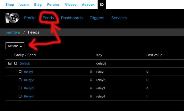
From the diagram, you can see that I have created four feeds and named them “Relay1”, “Relay2”, “Realy3”, and “Relay4”.
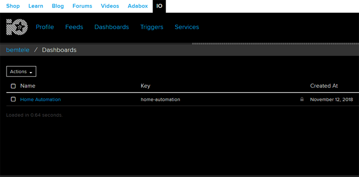
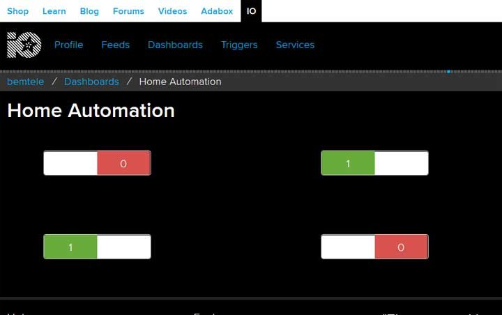
After creating the feeds, click on the Dashboards tab in the same submenu at the top of the page. Follow the same steps as you did for the feeds. Refer to the snapshot below.
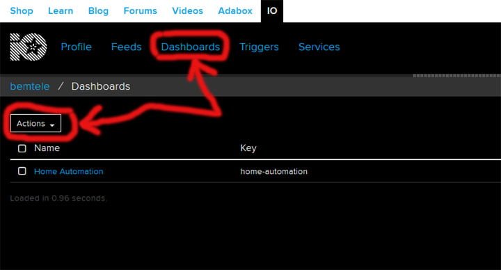
Click on the Actions drop-down menu button and select Create a new dashboard. As you can see from the above image, I created a dashboard and named it “Home Automation“.
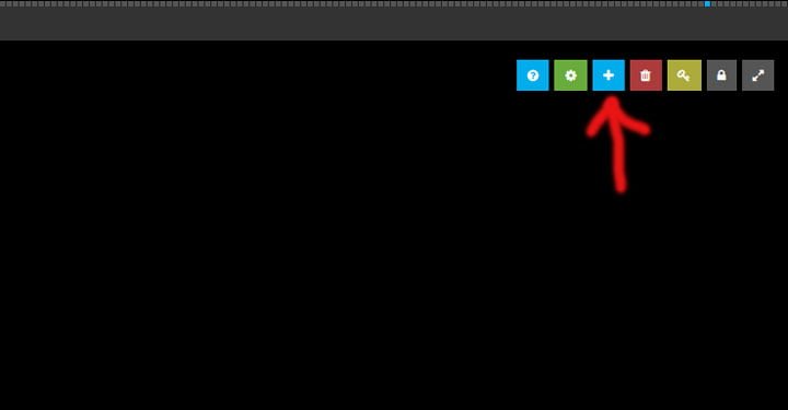
After creating the new dashboard, click on it and you should be redirected to a blank page where you can create your blocks. Adafruit IO blocks are the user or client interface components.
These include push-button, toggle switch, temperature sensor, streamer, indicator, etc. which can be used to control and monitor your IoT projects.
Start by clicking on the blue button with the + (plus) sign at the upper right and select the appropriate button or block.
In this project, I used the toggle switch as seen in the image below.
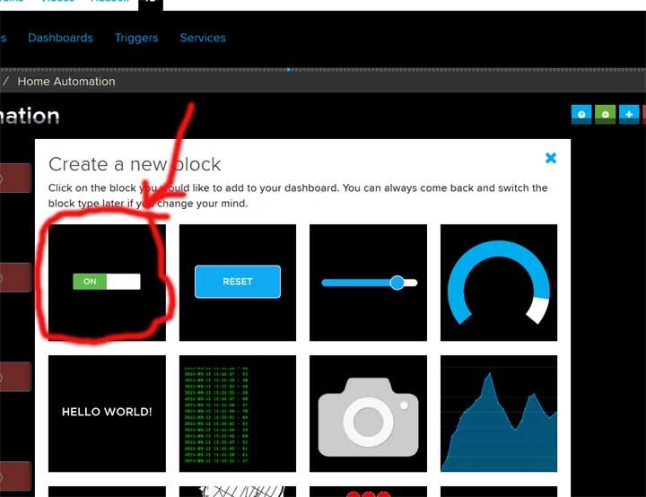
As soon as you click on the toggle button, you will be prompted to choose a feed. Select one of the feeds and click on Next. On the next screen, give the block a title.
It is not necessary though and you can just keep the default values.
But if you still want to name it then it is recommended to name it similarly to the name of the feed you assigned to it. Click on “create block” to finish creating the new block. Repeat the steps to create new blocks for the rest of the feeds.
Now click on either the AIO key link at the extreme upper right or the Key button next to the delete button.
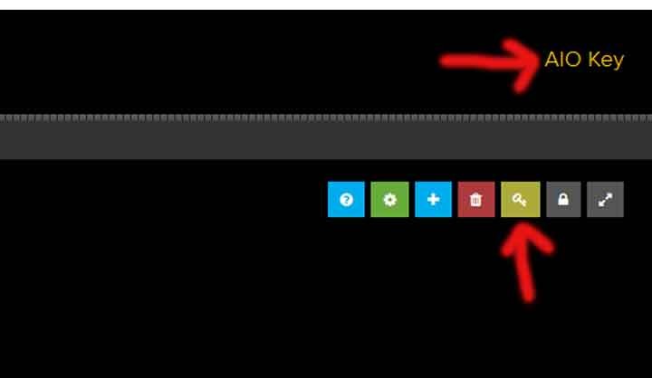
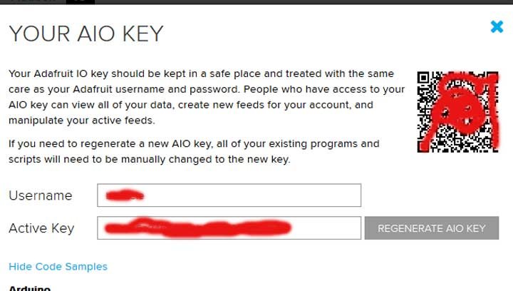
When you click on the AIO key link or button, the screen that opens contains your Adafruit access key and username as seen in the image below.
Please note down the Username and the Active key. They would be used to authenticate your nodeMCU to access your Adafruit MQTT feeds.
Congratulation!, You have successfully created an MQTT cloud control button for your first Internet of Things project. You will be able to integrate this cloud broker into your Google Home Appliance Control project.
Now let us program and connect the NodeMCU (ESP8266) to the broker.
STEP 3: ARDUINO IDE AND PROGRAMMING
Connect the NodeMCU to the computer USB port. If this is your first time working with an ESP wifi board (such as Nodemcu, Wemos, ESP-01, you will need to do some initial setup with your Arduino IDE. Read about starting ESP with Arduino IDE here.
Download the Adafruit MTTQ library to your PC from here. To install the downloaded library ( Adafruit MQTT Client ), In the Arduino IDE, go to Sketch > Include Library > Add .zip Library, locate the library, and click on Open.
After installing the library and ESP8266 core installation you can proceed to the next step.
Open this link, highlight and copy the code from the text editor to your Arduino IDE text editor and save. Now edit the sketch with your own credentials as shown below.
The code is pretty forward, with a few modifications you will be able to control your appliance with the google voice assistant app from your Android phone.
Let us go through the code in detail and edit it with our own credentials.
Below is the first code, this piece of code includes the necessary libraries. The first library activates the NodeMCU in-built WiFI connection using the generic Arduino language and the next two libraries also allow the board to connect and subscribe to the Adafruit MQTT feeds.
#include <ESP8266WiFi.h>
#include "Adafruit_MQTT.h"<br>
#include "Adafruit_MQTT_Client.h"
We define several parameters including WiFi credentials and Adafruit feed and authentication. Below is the code that holds your WiFi login. Edit it per your WiFi or Hotspot details.
#define WLAN_SSID       "Your router/Hotspot SSID"
#define WLAN_PASS       "your router/Hotspot password"
Input your WiFi name in the “Your router/Hotspot SSID” space and the password in the “Your router/Hotspot password” space. make sure you maintain the double quotes.
Also, note that the wifi name and password are case-sensitive. This means you have to check whether your WiFi name is in uppercase or lowercase.
The code below connects the NodeMCU to your Adafruit IO Account. Now paste or input the Username and the Active key saved previously to the “adafruit username” and “adafruit token key” fields respectively.
#define AIO_SERVER      "io.adafruit.com"   // dont change it
#define AIO_SERVERPORT  1883                   // use 8883 for SSL
#define AIO_USERNAME    "adafruit username"
#define AIO_KEY         "adafruit token key"
The following codes create WiFiClient and Adafruit_MQTT_Client objects. Since both codes are created outside void loop() and void setup(), they are known as global variables and can be called for at any instance in the code. The feeds for Relay1 through Relay4 are instantiated at this point.
WiFiClient client;
Adafruit_MQTT_Client mqtt(&client, AIO_SERVER, AIO_SERVERPORT, AIO_USERNAME, AIO_KEY);
Adafruit_MQTT_Subscribe Relay1 = Adafruit_MQTT_Subscribe(&mqtt, AIO_USERNAME "/feeds/Relay1");
Adafruit_MQTT_Subscribe Relay2 = Adafruit_MQTT_Subscribe(&mqtt, AIO_USERNAME "/feeds/Relay2");
Adafruit_MQTT_Subscribe Relay3 = Adafruit_MQTT_Subscribe(&mqtt, AIO_USERNAME "/feeds/Relay3");
Adafruit_MQTT_Subscribe Relay4 = Adafruit_MQTT_Subscribe(&mqtt, AIO_USERNAME "/feeds/Relay4");
In the setup function (void setup () ) several pins to serve as outputs to drive the relays were declared. Connection to WiFi Hotspot and MQTT server was also done.
void setup() {
Serial.begin(115200);
delay(10);
pinMode (5, OUTPUT);
pinMode (6, OUTPUT);
pinMode (7, OUTPUT);
pinMode (8, OUTPUT);


  Serial.println(F("Adafruit MQTT demo"));

  // Connect to WiFi access point.
  Serial.println(); Serial.println();
  Serial.print("Connecting to ");
  Serial.println(WLAN_SSID);

  WiFi.begin(WLAN_SSID, WLAN_PASS);
  while (WiFi.status() != WL_CONNECTED) {
    delay(500);
    Serial.print(".");
  }
  Serial.println();

  Serial.println("WiFi connected");
  Serial.println("IP address: "); Serial.println(WiFi.localIP());

  // Setup MQTT subscription for onoff feed.

  mqtt.subscribe(&Relay1);
}
The code above will connect the nodeMCU to the WiFi access point and the MQTT server, and then subscribe to the Relay1 feed (topic).
The code below is the main loop ( void loop () ), This code constantly monitors the feed subscription to make sure the nodeMCU is connected to the MQTT server and also perform the required function when it receives an update or change in feed topic.
void loop() {
  MQTT_connect();
  Adafruit_MQTT_Subscribe *subscription;
  while ((subscription = mqtt.readSubscription(5000))) {
    if (subscription == &Relay1) {
      Serial.print(F("Got_Relay1: "));
      Serial.println((char *)Relay1.lastread);
      uint16_t num = atoi ((char *)Relay1.lastread);
      digitalWrite (5, num);
    }
The final code is needed to connect and reconnect as necessary to the Adafruit MQTT server. This snippet was part of the example code provided by Adafruit when you installed the library.
void MQTT_connect() {
  int8_t ret;

  // Stop if already connected.
  if (mqtt.connected()) {
    return;
  }

  Serial.print("Connecting to MQTT... ");

  uint8_t retries = 3;
  while ((ret = mqtt.connect()) != 0) { // connect will return 0 for connected
       Serial.println(mqtt.connectErrorString(ret));
       Serial.println("Retrying MQTT connection in 5 seconds...");
       mqtt.disconnect();
       delay(5000);  // wait 5 seconds
       retries--;
       if (retries == 0) {
         // basically die and wait for WDT to reset me
         while (1);
       }
  }
  Serial.println("MQTT Connected!");
}
Connect the NodeMCU to your computer and upload the code. When the upload is successful, switch on your router or phone hotspot and open the Arduino IDE serial monitor.
If you carefully followed the instructions above and if everything went well you should be greeted with “connected to Adafruit.io” in the serial monitor. Check the image below
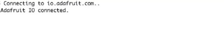
Now, open your Adafruit dashboard and flip the toggle switch on and off while watching your serial monitor. You should see “Relay1 to Relay4” toggling from 0 to 1 in response to a switch state change on the Adafruit dashboard.
Congratulations!, you have successfully linked your IoT project to the Adafruit server. There is no stopping now! yes, it’s time to talk to the project. Now, let’s link the Adafruit server to the Google voice assistant.
STEP 4: CONNECTING TO GOOGLE ASSISTANT USING IFTTT
To make a connection between the Adafruit IO and google assistant for voice control, we need a platform called, IFTTT ( If this then that). As discussed earlier, this platform allows countless platforms and different services to trigger actions or control signals to manipulate other services.
If you have not created an account yet, kindly open this link and register for a free account. Then log in to your IFTTT dashboard. Since this is your first time on the platform, click on the “Explore” at the upper right and then the “Add + button” as seen in the image below.
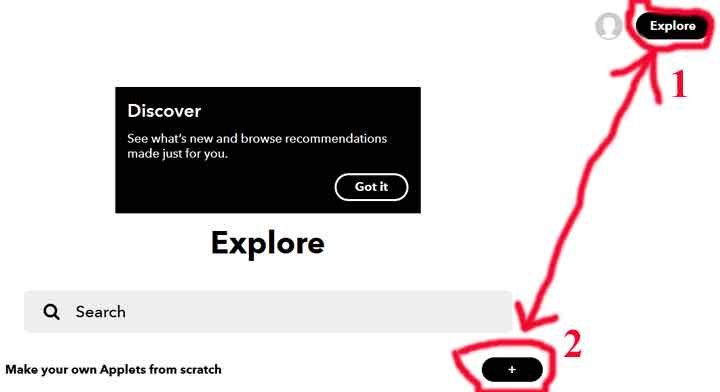
You should be taken to the “create a new applet” window. Alternatively, you can also click on this link to directly access the window if you are finding it difficult to locate the “create your own button“.
This window has the applet editor, where you can choose a particular trigger (“If This“) and the corresponding action (“Then That“).
Start by click on the + (plus) which comes after the “If” as seen below.

Search for “Google Assistant” and choose it as your trigger service. If this is your first time using the IFTTT platform, you will be directed to connect to your google account.
Click on connect and select the google account you will use for the google voice assistant on your phone and accept the permission (click on allow). You should be redirected back to the IFTTT platform. Now, select “Say a simple phrase” as a specific trigger.
You will be prompted with a new list of fields to fill in. This includes variations of the trigger phrase and the Google Assistant’s response as well as the language.
Referring to the image below you see that I wrote “Turn on relay one“, “turn relay one on” and “relay one on” as my trigger phrases.
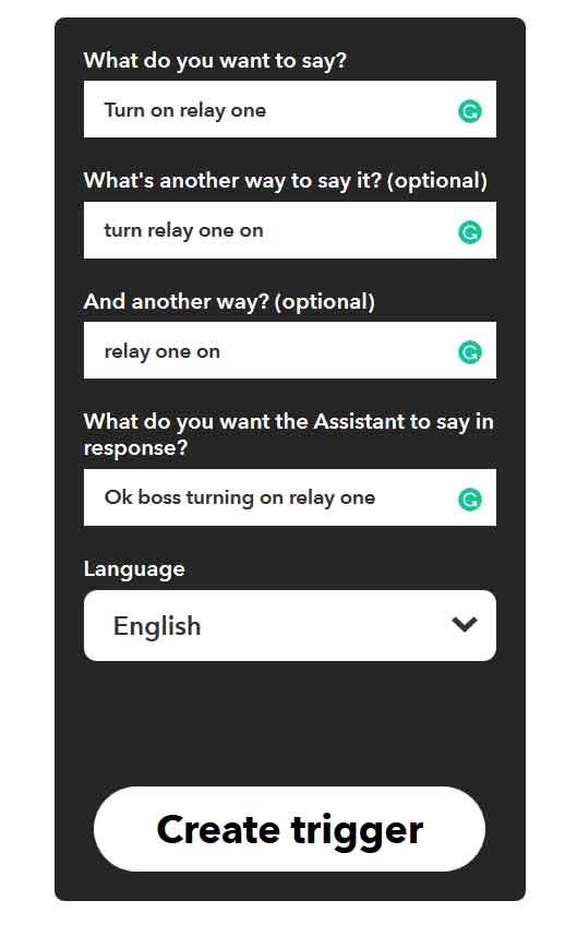
However, you can choose to write any phrases you like, something “switch on light one” or “switch on bedroom light“. Write what you will want google assistant to say when you command it with a trigger ( I chose “Ok boss turning on relay one” ).
Then choose your preferred language and finally click on “Create trigger“.
On the next page click on the + button that comes immediately after the “Then“. Check the image below.

You should be redirected to choose an Action. The applet “action” is the recipient of your trigger. For this Google Home project to work, Search for “Adafruit” and select it.
Since this is your first time on the platform, you will be prompted to connect to Adafruit. Click on the “Connect” button and log in (if you have logged out from the adafruit dashboard) to accept the connection.
After allowing the connection, you will be redirected to the IFTTT platform.
Now, choose (click on) “Send data to Adafruit IO” as your specific “Action“
On the next page, you will be prompted with two fields as can be seen on the image below;
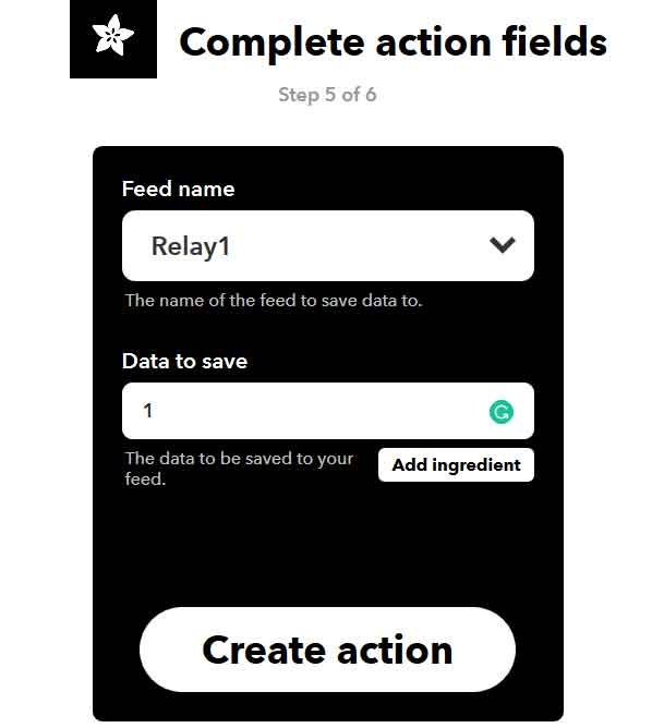
The first field should fetch all your feeds from Adafruit for you to select the one you want to send the control signal (data) to. I selected “Relay1” as my feed name. If your feed has a different name, please select that.
The other field is the data to be sent. Type in “1” which is part of the controlled commands the NodeMCU is waiting for.
Click on “Create Action” and then the “Finish” button.
After creating the first applet for turning on the relay1, create another one for turning off the relay. The procedure is just the same except you will use a different phrase, something like; “Turn off relay one” instead of “Turn on relay one”.
Moreover, after selecting your feed, you will use “0” as your data instead of “1”.
Now, in your IFTTT
You can repeat the steps to get as many applets as you want. For this tutorial, I created eight (8) applets (four applets for turning on relay1 through relay4 and the other four applets for turning them off).
That’s it, you have a complete IFTTT applet linked to both Google Assistant and Adafruit IO.
Now, connect your phone to the Google Assistant. This can be done in many ways, but for most Android users, touching and holding the home button will quickly bring up the Google Assistant.
( you may also search on Google how to connect your specific device to google assistant)
In some cases, if you are unable to connect to the assistant, you can also use the Google messaging app which includes the Google Assistant.
Open the assistant with the Google account used for activating the IFTTT page. As soon as you are welcomed by the pretty voice of the Google Assistant, just say the trigger phrase used for the IFTTT trigger.
Now watch the Google assistant majestically reply to you and then send the corresponding data to control your NodeMCU.
Congratulations!, you now have a complete Google Home Appliance Control system that uses voice to control your NodeMCU.
Now that you have acquired the basic information on voice-controlled IoT projects using the MQTT server, you can modify the code, hardware, procedure, and instructions to make a variety of voice-controlled IoT devices.
Comment below if you have any questions, or suggestions or if you face problems constructing this Google Home Appliance Control project.