Introduction
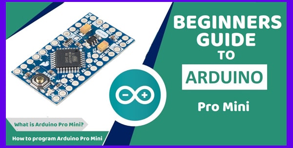
What is an Arduino Pro Mini development board? The Arduino Pro Mini is a compact microcontroller board that, like its other popular variations, such as the Arduino UNO and Arduino Nano, employs the famous AVR Atmel Atmega328p microcontroller chip.
Because it uses the same Atmega328p microcontroller chip as the Arduino Uno, this microcontroller board has the same capabilities. This board’s tiny size and affordable price make it more appealing compared to the huge and expensive Arduino Uno board.
Types of Arduino Pro Mini Board
Even though the Arduino Pro Mini comes in two main flavours, the working principles and coding are the same. We have the 3.3V board with an inbuilt crystal oscillator running at 8MHz and the 5V board with an inbuilt crystal oscillator of 16MHz.
As the name suggests, the 5V version of the Arduino Pro Mini includes a 5V regulator and a 16MHz crystal oscillator clock on the board. In contrast, the 3.3V version has a 3.3V voltage regulator and an 8MHz onboard crystal oscillator.
For additional information on the Arduino Voltage Regulator, see the following topics.
The difference between 5V and 3.3V versions of the Arduino Pro Mini boards.
How can I tell whether my Arduino boards support 5 or 3.3 volts?
Can I use 5V on a 3.3V Arduino Pro Mini board?
Check these recommended post:
Pinout of the Arduino Pro Mini Board
The figure below shows the comprehensive, thorough, and cross-verified pinout of the Arduino Pro Mini Board. The light green represents the chip’s corresponding PIN for programming.

The table below also has a detailed description of each colour shown on the pinout diagram above. It indicates the section used as ports, SPI communication, PWM pins, i2C pins etc.

Arduino Pro Mini Board Features
The Arduino pro mini board has the following features:
1. It has 14 Digital Input/Output (I/O) pins
There are 14 digital I/O pins on this board, 6 of which may be utilised for PWM output. These pins are identified on the pinout diagram and the detailed description table. T0 and T1 timers are connected to the board’s digital I/O Pins 4 and 5.
Furthermore, Pins 2 and 3 have hardware-dedicated interrupt capabilities. Still, you may utilise the other 14 digital I/O pins as interrupts.
We will also cover tutorials for using any digital pins to perform interruption.
2. The Pro Mini has 8 Analog Pins
The pro mini comes with an Atmel328 chip. The chip is soldered using surface-mounted device (SMD) technology. It contains an 8-channel Analogue to Digital Converter (ADC) that can interface eight separate analogue sensors at the same time.
The Analog input Pins A4 and A5 can also be used for the I2C communication protocol. Furthermore, the first six Analog pins can be used as interrupts.
3. On-board voltage regulator
Like the Arduino Uno, Nano and Mega, the Arduino pro mini also has an inbuilt voltage regulator. However, the voltage regulator for the Arduino Pro Mini is either 3.3 or 5 volts. Voltage Regulator allows you to power your Arduino Pro Mini boards with a 5 to 12-volt unregulated voltage source.

The voltage regulator is used to identify the variant of the board. If you see 50 written on the voltage regulator, as shown in the image above, it means the board is a 5v type. On the other hand, if you see 33 printed on the regulator, it means the board is of 3.3V type.
4. It has an 8MHz or 16MHz Clock Frequency
The 3.3-volt Arduino pro mini board contains an 8MHz inbuilt oscillator, but the 5-volt type includes a 16MHz oscillator. Most Arduino Pro Mini boards use a ceramic oscillator; however, I have also seen Arduino Pro Mini boards with a crystal oscillator. You can get more information about oscillators on this page.
5. There is no USB port or onboard programmer
Unlike the Uno, Nano and Mega, the Arduino Pro Mini does not include a USB port and no onboard programmer. As a result, you’ll need to programme it with an external USB to a TTL programmer. For some people, like myself, excluding the programmer and USB port gives the board some layers of security.
6. The Arduino Pro Mini has no soldered connectors
Even though the Arduino pro mini comes with connectors, they are not attached to the board during manufacturing. Since the connectors are not soldered, you can solder only the pins required for your project, making your circuit more compact.
7. Built-in Led
A built-in LED is connected to the SPI serial clock (SCLK, Pin 13) of Arduino pro mini. This LED will blink when Arduino Uno is connected to an SPI programmer. Even though pin 13 is used for the built-in LED, you can also use it as a digital input or output Pin.
Onboard Microcontroller Chip (Atmega328p)
The table below shows the features of the onboard Atmega328p microcontroller chip.
| FEATURE | DESCRIPTION |
|---|---|
| 32KB Flash Memory | The sketch or code is stored on the board in the 32KB of flash memory provided by the Atmega328. Since this memory is nonvolatile, the code (sketch) that we have flashed will remain there even if power is lost, and it will reload as soon as power is restored. |
| 1KB EEPROM | The Atmega328p chip comes with 1 KB of electrically erasable read-only memory. This memory can be utilised for storing data over time by the microcontroller. It is a nonvolatile memory, which means the data stored in the EEPROM will stay there even if the power is lost. |
| 1KB of RAM | The Atmega328p microcontroller has 2KB of SRAM. This memory is used by the code while it is executing. The information in the memory is lost when the power is turned off. When the power is restored, the code starts executing from the beginning. The contents of RAM are therefore repopulated again. |
| 32 8-bit Register | The Atmega328p chip has 32 8-bit general-purpose registers. |
How to program the Arduino Pro Mini
You can program the Arduino Pro Mini by using the existing Arduino IDE (integrated development environment). The IDE includes a compiler to convert your sketch (code) into binary. It also has an uploader (avrdude) that uploads the hex binary file onto the board.
To program the board, you have to connect the Arduino Pro Mini to the computer. However, this board doesn’t have any USB ports or an onboard programmer.
Therefore, you need a USB to serial converter (FTDI, USB to TTL serial module). You can also use another Arduino board (Arduino Uno or Arduino Mega) to serve as a programmer. Another way to program the Arduino Pro Mini is through the SPI port using a USBASP programmer.
Pin Description
To program the pro mini board and use it for engineering projects we need to know all the pins and thir usage. The table below shows the pins and their description.
| PIN NAME | PIN DESCRIPTION |
|---|---|
| Raw Pin | This pin is used to power the Arduino pro mini from an external power supply. You can connect this pin to an unregulated power supply between 5 and 12 volts. |
| GND Pins | All of the GND pins provide common connections to the different sensors interfaced with the Arduino Pro Mini board. Also, all of these pins are shorted together. You can power the Arduino Pro Mini with an external power source (such as a battery or DC adaptor). To do that, you have to connect the negative terminal of the supply to any of the ground (GND) pins. |
| Vcc Pin | The VCC pin is connected to the output of the onboard voltage regulator. You can use it to power sensors or other modules such as LCDs and ultrasonic sensors. The pin can also be used to power your Arduino Pro Mini board. However, depending on the type of Arduino Pro Mini board, the voltage should either be 5V or 3.3V. Note that the onboard microcontroller will burn if you use a power supply that exceeds the rated voltage (3.3V or 5V). |
| Digital & PWM Pins: | The Arduino Pro Mini has 14 digital input/output pins. Of these pins, you can use 6 as PWM (Pulse Width Modulation) outputs. The pins 3,5, 6, 9, 10, and 11 provide PWM output. These pins are used for controlling the speed of a motor or producing analogue outputs when necessary. |
| Analog Pins | The Arduino Pro Mini has 8 analogue pins labelled as A0 to A7. These pins are used to receive external analogue signals such as temperature. The analogue signals applied to these pins are converted into a 10-bit digital value using an internal ADC (Analogue to Digital Converter). |
| TX & RX Pins | The TX and RX pins are used by the internal USART (Universal Synchronous/Asynchronous Receiver/Transmitter) circuit on the atmega328p chip, and these pins can be used to interface the Arduino Pro Mini with other devices using the UART protocol. |
| Reset Pin | The reset pin is connected to the reset button on the board. You can use this pin to reset the microcontroller. This is done by applying a logic low voltage or GND for a short time. When you do that the microcontroller will restart the program. |
| FTDI Header | The FTDI header is used for programming the ATmega328p using the USART module. These pins include TX, RX, DTR, VCC, and GND. The TX and RX are discussed above. Also, the VCC and GND pins of the FTDI header are used to power the Arduino Pro Mini while uploading the code. Again, the DTR (Data-Terminal-Ready) pin is used by the FTDI programmer to auto-reset the Arduino Pro Mini for uploading a new code. |
| SPI Pins | The SPI (Serial Peripheral Interface) pins allow the microcontroller to communicate with sensors and other devices using the SPI protocol. They include Pin 10 (SS), Pin 11 (MOSI), Pin 12 (MISO), and Pin 13 (SCK). |
| I2C Pins | The I2C standard allows the use of only two cables to send and receive data from many sensors and other modules. The analogue pins A4 and A5 are also connected to the I2C communication bus. The analogue pins A4 and A5 are also connected to the I2C communication bus. Using this protocol, the data is sent on the SDA, whereas the SCL is used for clock synchronization. |
Arduino Pro Mini vs Other Arduino boards (Uno, Nano, Mega etc.)
The tiny nature of the Arduino Pro Mini makes it stand apart from the other AVR boards. However, the main shortfall of this board is the lack of a USB interface and an onboard programmer. You will, therefore, find it a little difficult to program the board if you are a complete beginner. This is, however, not the case if you have some experience in soldering.
The Pro Mini is more practical for use in embedded systems. But unlike the Arduino Uno or Mega, you can’t interface the Pro Mini with sensors without hardwiring them to the board.
Applications of the Arduino Pro Mini
Like a regular Arduino board, you can use the Pro Mini in a wide variety of applications. The small form factor makes it stand out when compared to the other boards. That said, you can use this board in the following applications:
- Embedded Systems
- IoT applications
- Home Automation
- Display Systems
- Robotics


Comments 1