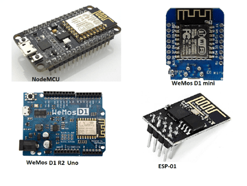
The NodeMCU and Wemos D1 R2/mini development boards use the well-known ESP8266 ESP8266 Development Board WiFi chip. The ESP8266 appears to be programmable in the same way that any other microcontroller such as the Arduino Uno is.
Its clear advantage over the Arduino or PIC is its ability to connect to the Internet via WiFi. The ESP8266 Wi-Fi board, on the other hand, has limited pins, despite the fact that the chip itself has a plethora of output ports.
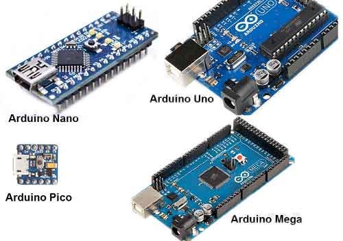
The NodeMCU overcomes this limitation by including ten GPIO pins capable of generating PWM, I2C, and a 1-wire interface. This ESP8266 development board closely resembles an Arduino Nano.
Another advantage of this board as an Arduino is that you can program it directly from your PC or Mac! That is exactly what I will demonstrate in this tutorial. Let’s cross our fingers and follow the steps below.
Recommended Posts:
Step 1: Insert your ESP8266 Development Board into your computer USB port
To connect the board, you’ll need a USB port micro B cable. After connecting the board to the USB port, the blue LED on the board began to flash. The device driver for your board should have been installed by now. If your computer isn’t detecting the board, you might need to download and install the driver from this page.
Step 2: Launch the Arduino IDE
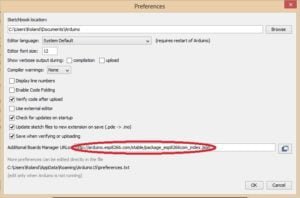
Download and install the most recent Arduino IDE from arduino.cc. If you already have the IDE installed, make sure your version is at least 1.6.4 before proceeding. Navigate to File > Preferences.
The preferences window will appear, and in the “Additional Boards Manager URLs” field, type (or copy-paste) the following link without the quotes: “https://arduino.esp8266.com/stable/package_esp8266com_index.json“. To close the window, click OK. check the diagram below.
Then navigate to Tools > Board > Board Manager. Scroll down to the entry “esp8266 by ESP8266 Community.” Look for the install button in the lower right corner after clicking that entry.
Wait for the installation to complete. Congratulation! The ESP core board library is now installed and integrated into the Arduino IDE. You can now begin tinkering with your Wi-Fi board.
Step 3: Test your ESP8266 Development Board, Make an LED blink.
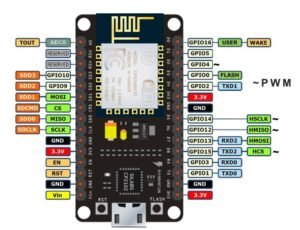
Let’s put our ESP Wi-Fi board to the test by making an LED connected to one of the digital pins blinks. But first, you should be aware that the pin names printed on the board and the pin names we’ll be using for our program differ slightly. I’m working with NodeMCU V1.0. See the pinout diagram below.
In this tutorial, I wired the LED to D7, as shown on the NodeMCU Esp8266 board. As seen in the image above, D7 represents GPIO13. The following code is essentially the Blink sketch from the Arduino example:
// the setup function runs once when you press reset or power the board
void setup() {
  // initialize digital pin 13 as an output.
  pinMode(13, OUTPUT);
}

// the loop function runs over and over again forever
void loop() {
  digitalWrite(13, HIGH);   // turn the LED on (HIGH is the voltage level)
  delay(1000);              // wait for a second
  digitalWrite(13, LOW);    // turn the LED off by making the voltage LOW
  delay(1000);              // wait for a second
}
Enter or copy the code above into the text editor pane of the Arduino IDE. Press the upload button. If everything is in order, the “Done Uploading” text will appear beneath the IDE text editor.
Bingo! here we are, it worked!
Even though I used the nodeMCU for this tutorial, the Wemos d1 mini, and the Arduino wifi can also be used. If you have any problem connecting the ESP8266 Development Board, esp8266 esp 12e development board, Nodemcu esp8266 development board, or Wemos esp8266 development board to the Arduino IDE, use the comment box to ask for help.
You may also read more about Arduino programming from this link.




Comments 1